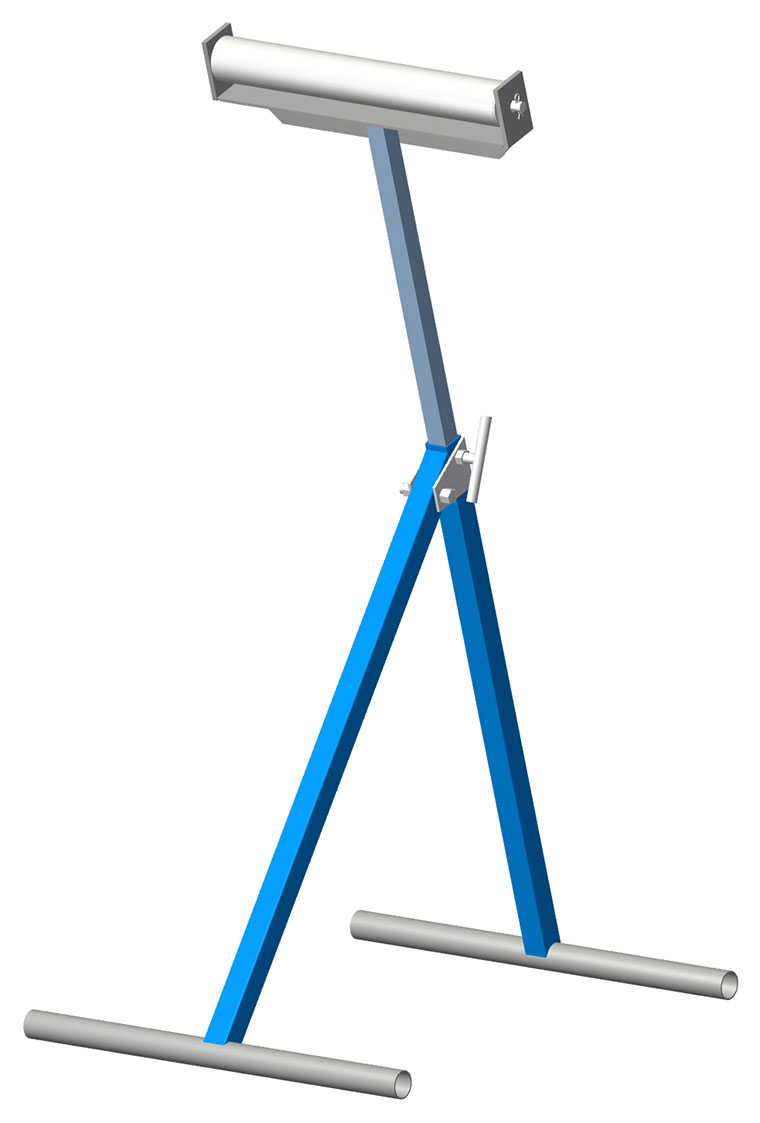
The conveyor roller stand is a handy addition to your workshop equipment. You may wish to change the overall size of the roller stand to suit your own needs. The shs size can be changed to a larger size if you need a sturdier version.
Free Conveyor Roller Stand Plans
| Materials Required | |||
|---|---|---|---|
| Item Number | Material | Length | Quantity |
| 1 | 25x25x1.6 SHS | 600mm | 1 |
| 2 | 25x25x1.6 SHS | 530mm | 1 |
| 3 | 20NB pipe | 4200mm | 2 |
| 4 | 10mm round bar | 80mm | 1 |
| 5 | 50x3 flat bar | 55mm | 2 |
| 6 | 20x20x1.6 SHS | 600mm | 1 |
| 7 | 40x40x3 angle | 325 | 4 |
| 8 | 40x5 flat bar | 60 | 2 |
| 9 | 32NB pipe | 315 | 1 |
| 10 | 10mm round bar | 360 | 1 |
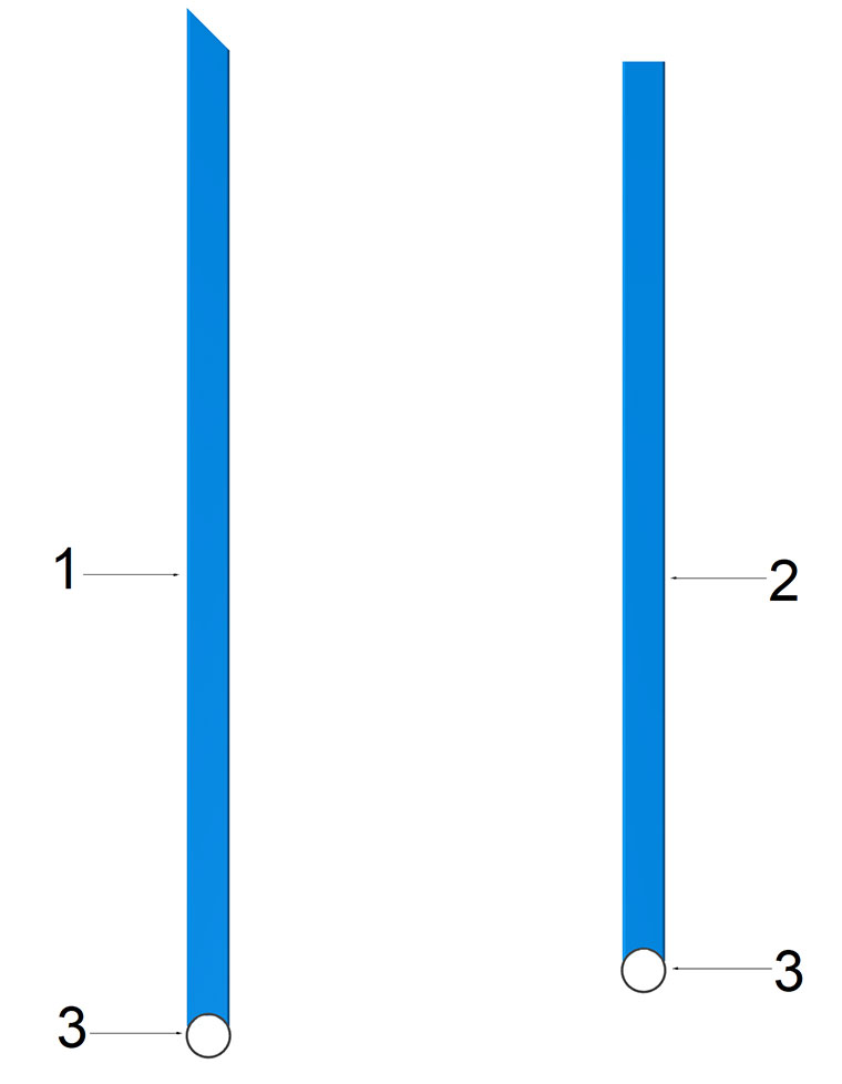
Diagram 1
1. Begin by cutting all of the steel as indicated in the cutting list. Label each with the item number on it using a marking pen and set aside.
2. Using the 20nb pipe (item 4) as a guide, mark and cut one end of both items 1 and 2 so that they fit neatly around the pipe. Refer to diagram 1. The cuts may be done with a cutting disc, bandsaw, hacksaw, etc.
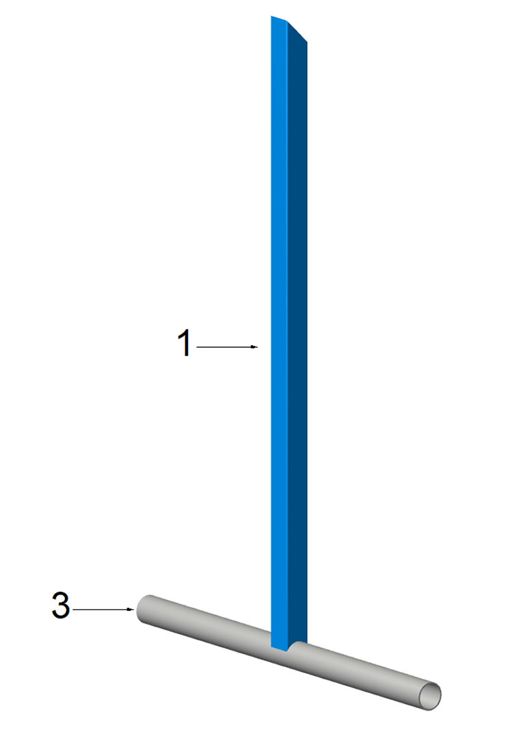
Diagram 2
3. Weld item 1 and item 2 onto the centre of the 20nb pipe. Refer to diagram 2.
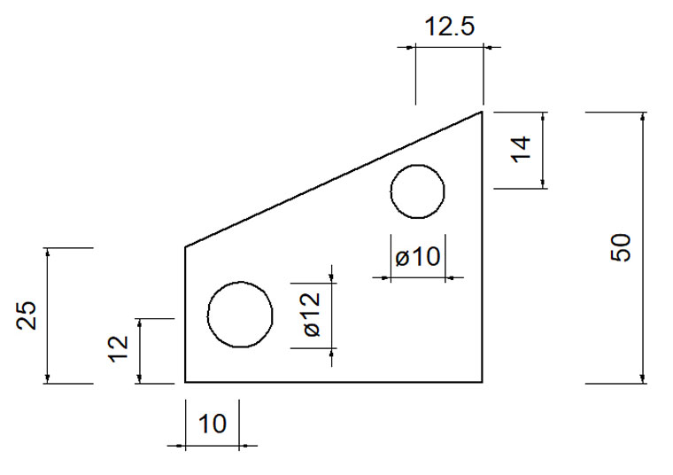
Diagram 3
4. Cut and drill item 4 as shown in diagram 3. Two of these are required but only one needs to have a 10mm hole drilled.
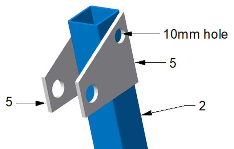
Diagram 4
5. Weld items 5 onto the top of item 3. Ensure that the two 12mm holes are lined up with each other. Refer to diagram 4.
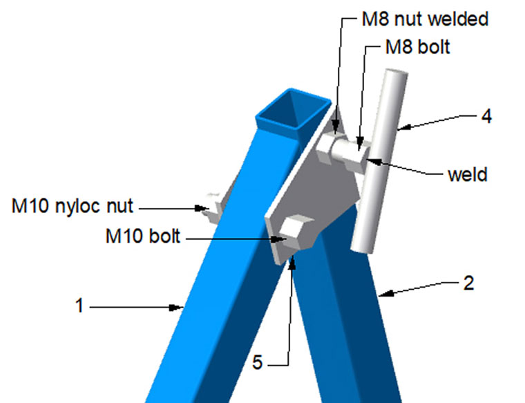
Diagram 5
6. Drill a 10mm hole through item 5 into one side of the shs only. Refer to diagram 4. Weld an M8 nut over the centre of the 10mm hole in the flat bar (item 5). Check that an M8 bolt will screw into the nut, through the flat bar 10mm hole and through the shs.
7. Weld the head of the M8 bolt to the centre of the 10mm round bar (item 4). Refer to diagram 5. Screw this into the welded M8 nut. Drill a 12mm hole through the shs (item 1) for the M10 bolt and nyloc nut.
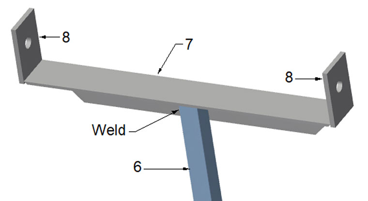
Diagram 6
8. Drill a 12mm hole in each of items 8 (40x5 flat bar). The position of hole will depend on the diameter of the pipe that you are using for the roller. If you are using the suggested size, the centre of the hole should be approximately 35mm up from the lower edge of the 40x5 flat bar, to give approximately 10mm clearance between the pipe and the angle. Refer to diagram 6.
9. Weld items 8 to the ends of the angle (item 7) as shown in diagram 6.
10. Weld the 20x20 SHS (item 6) into the centre of the angle. Refer to diagram 6.
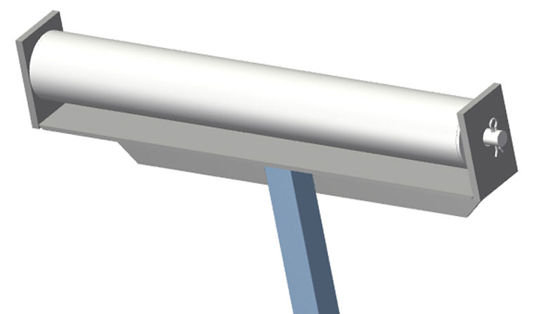
Diagram 7
11. For this step, two washers are required. These should have a hole diameter of approximately 12mm and an outside diameter to match the outside diameter of the pipe. Weld the two washers onto the ends of the pipe (item 9).
12. Drill a small hole into each end of the 10mm round bar (item 10), approximately 5-10mm in from the ends.
13. Install the pipe roller as shown in diagram 7 and secure by inserting an “R” clip or split pin into each of the holes.
14. Insert the 20mm shs (item 6) into the 25mm shs (item 2) and check that it slides smoothly up and down and that the locking bolt secures it at the correct height.
15. Clean any welds using a grinding disc or flap disc and paint as required.